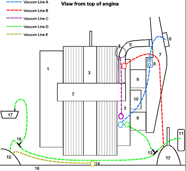
This is a vacuum diagram for the UK-spec (right-hand drive) XJ6 Series II (non-emissions controlled), showing the vacuum piping in the engine compartment. I've based it on what is in my car, plus whatever should be there but isn't (yet). If anyone has any corrections or comments, please let me know.

| Item | Description |
| 1 | Exhaust manifold |
| 2 | Over-engine warm air duct |
| 3 | Inlet manifold |
| 4 | Distributor and vacuum advance unit |
| 5 | Pipe from warm air duct to air cleaner housing |
| 6 | Vacuum actuator for warm air flap on air cleaner housing |
| 7 | Air cleaner housing |
| 8 | Temperature control for (6) - this device will let vacuum through when air is cold, and block the vacuum when warm. |
| 9 | SU HIF7 carburettors |
| 10 | AED unit |
| 11 | Vacuum reservoir (on other side of LHD vehicles) |
| 12 | Brake booster (on other side of LHD vehicles) |
| 13 | T-connector for vacuum lines |
| 14 | Water valve |
| 15 | Connectors through firewall to climate control system. The large connector connects to vacuum line (D) and the small connector to (E). |
| 16 | Firewall |
| 17 | Speed control bellows (Speed-O-Cruise is the brand which was factory fitted to my Jag) |
| 18 | T-connector between vacuum line (D) and the vacuum line to the speed control bellows. |
| Vacuum line A | This is two separate lines. The first runs from underneath the inlet manifold (3) to a connector on the bottom of the little square temperature sensor (8), and another line runs from the other connector on (8) to (6). Basically, what happens is this: a bi-metal strip in (8) opens the vacuum connection through (8), so when the engine is started, the vacuum will cause the flap at (6) to open, and warm air from the exhaust manifold (1) will travel through (2) and (5) into the air cleaner, improving cold running. As the temperature at (8) starts increasing the flap will begin closing, until it's fully closed. |
| Vacuum line B | This vacuum line runs from the underside of (3) through a one-way valve (if I'm not mistaken) to the brake booster. This line is part vacuum tubing and part steel pipe. |
| Vacuum line C | This line runs from the top of the inlet manifold down to the vacuum advance unit on the distributor. To test if the vacuum advance is working, remove the distributor cap, and suck on line (C). The plate, condenser and points in the distributor should move. |
| Vacuum line D | Line (D) runs from the underside of (3) to a T-connector (13). From there, one line goes to the vacuum reservoir (11), and another line goes to the T-connector at (18). From (18), one line goes to the large connector on the firewall (15), while the other goes to the speed control bellows (17). |
| Vacuum line E | Line E runs from the small connector at (15) to the water valve, which is mounted on the firewall directly behind the engine. |
Copyright ©1999 G R Adamson
Last updated: 30 August 1999